PLAttice
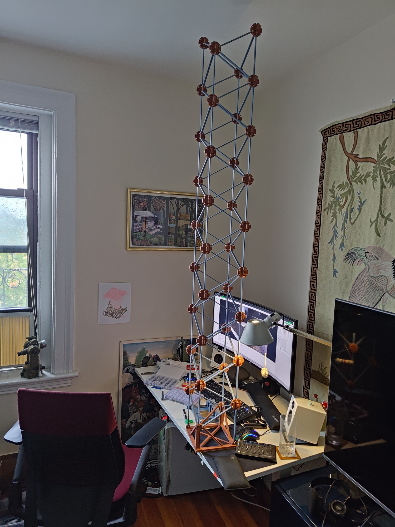
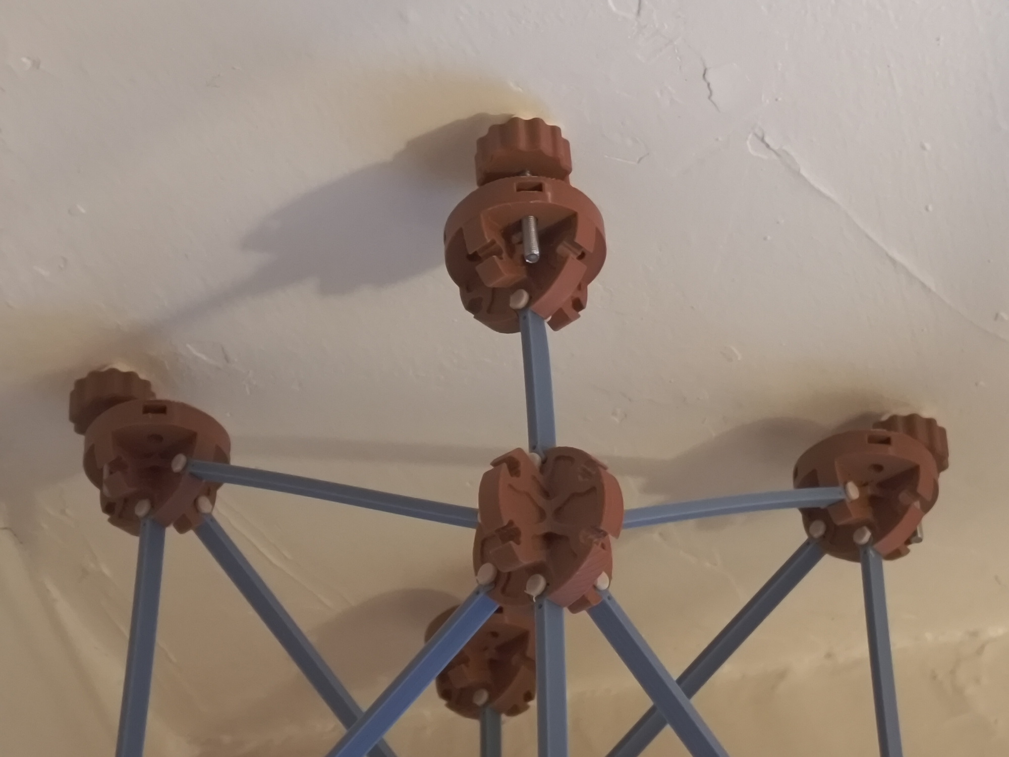
PLAttice: it's an assembled lattice, built entirely out of 3D printed parts made from PLA. The name could also be short for Plastic Lattice, I suppose. PLAttice is composed of struts, nodes, and pins; in this example, these three part types are grey, brown, and ivory colored, respectively. The pins are slightly tapered and hold the struts into the nodes using what I sometimes call orthogonal taper pin joints, previously demonstrated in metal and wood. PLAttice came about because I got a new personal 3D printer and wanted to reversibly construct structures substantially larger than the print bed. The project succeeded nicely, with a PLAttice square box truss weighing around 800 g/m (roughly equivalent to 2x2 lumber) and being capable of spanning up to around 4 m before buckling. The struts are far and away the weakest member, failing in compression long before the joints or nodes give out; a reasonable iteration would relax the PLA-only requirement and use a different material (like bamboo dowels) for these elements, or at least beef up their width a bit.
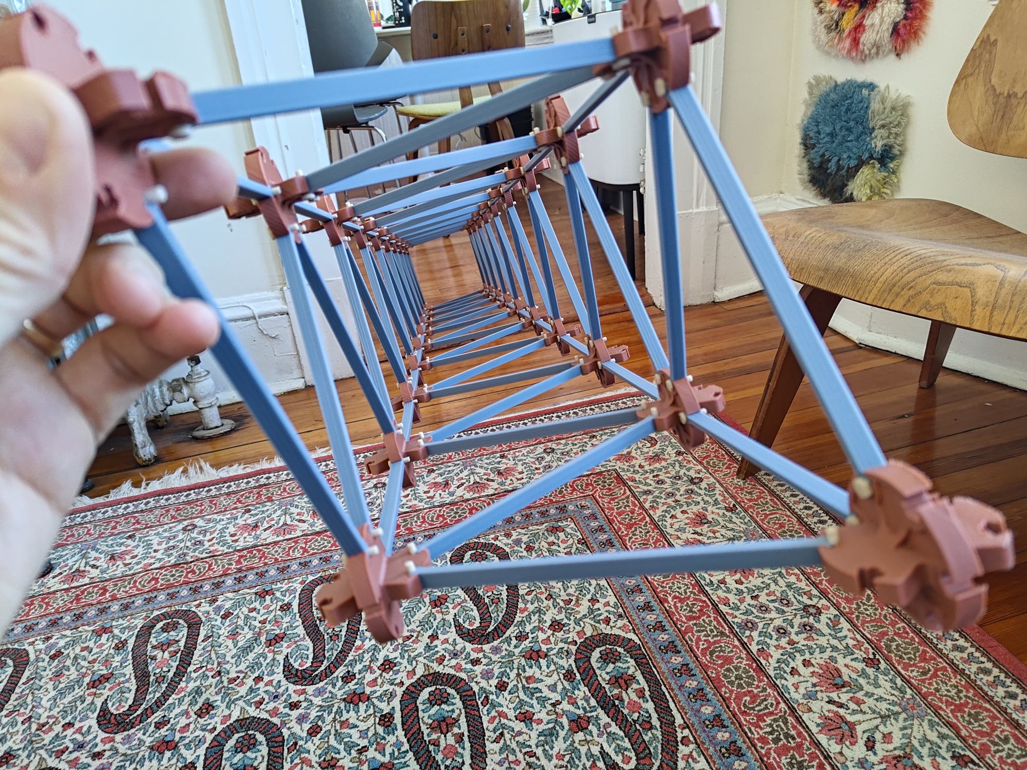
PLAttice doesn't form cubic crystalline structures; instead, it's designed to make square box trusses that can double up side-to-side or branch off at 60 degree angles as needed. In that way it's somewhat more anisotropic and limited as compared to systems based on cubic stacking arrangements, but works well for forms that are long and spindly and perhaps a bit tree-like. The nodes each host up to ten struts, but in practice a typical box truss only uses six joints per node. This tiling keeps nodes relatively small and makes eight of the ten pins easy to install and remove; the last two have to angle a bit during insertion to clear support tabs, but they aren't too bad with a bit of practice.
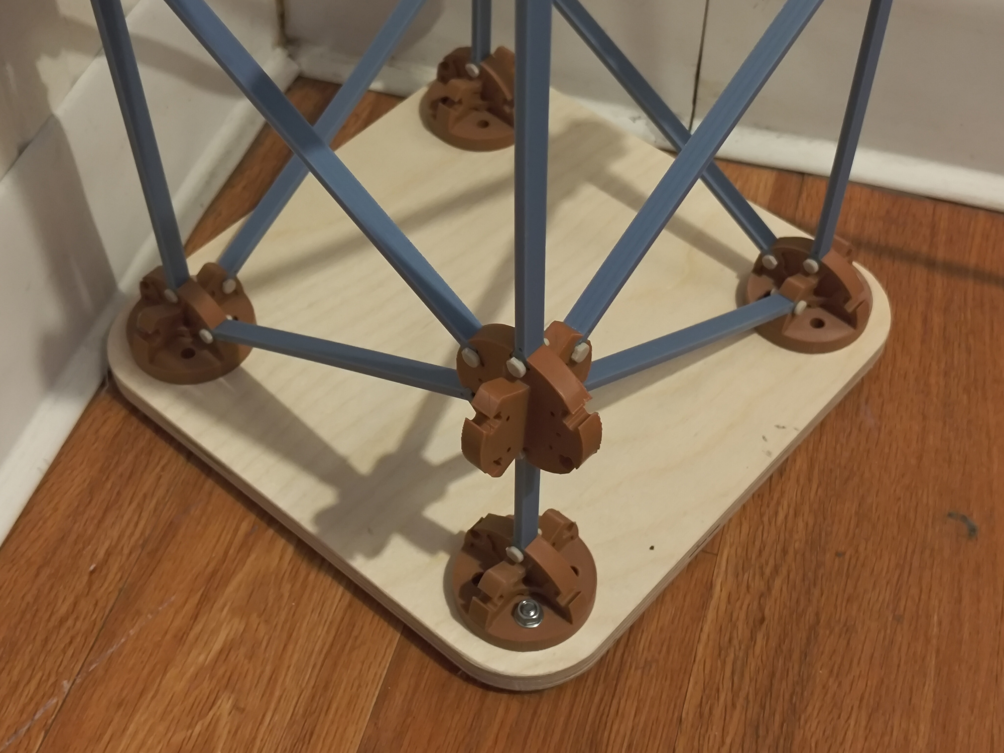
In addition to the three core parts, there are a few extra bits that help structures fit into the built environment. End nodes and short struts square off the end of a box truss, and can be bolted onto a routed plywood panel to make a nice foot, backed up with self-adhesive rubber pads for extra friction against the floor:
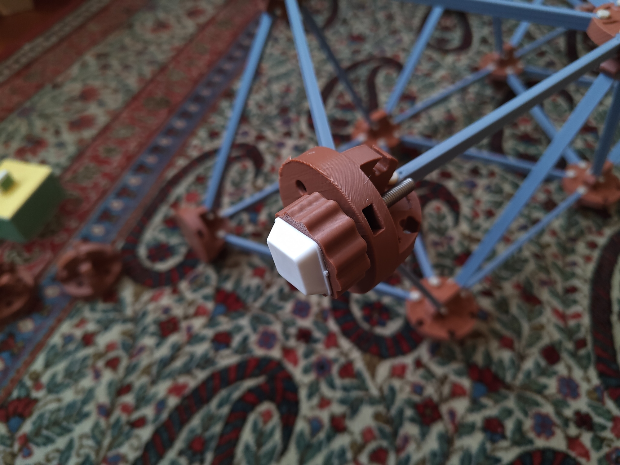
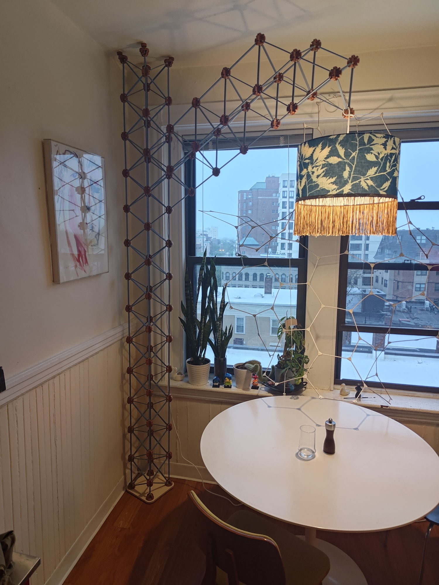
On the upper side, slightly modified end nodes capture M5 nuts, and an adjustable foot with an M5 button head bolt and another nut allow columns to gently wedge themselves into rooms. The feet also include a self-adhesive rubber pad for ceiling friction. In practice, installing the feet isn't terrific, since the pad rotates during adjustment, causing the tower to walk around a bit; I also went a bit too high on the design, so the feet bound up when I tilted the tower upright and required a bit of extra persuasion. But they do seem to work well enough:
This all comes together nicely when one needs an overhead lamp for a kitchen table but doesn't want to put a fussy hook into the ceiling. This is totally simpler, I promise! I bought the lovely cyanotype shade seen here from Sri Thumati at the 2025 Somerville Open Studios art walk; her work is really the star of the show, with the organic silhouettes of inverted oak leaves creating dramatic contrast against the regular spacing of the PLAttice struts. Given the long cantilever, I advise waiting to build anything similar until mine has survived for at least a few months; we know PLA moves a bit when it is left under strain, and the direct sunlight through non-UV-treated windows certainly won't help either. I'll update this post if it all keels over, but for now the lamp is exactly what I hoped it would be:
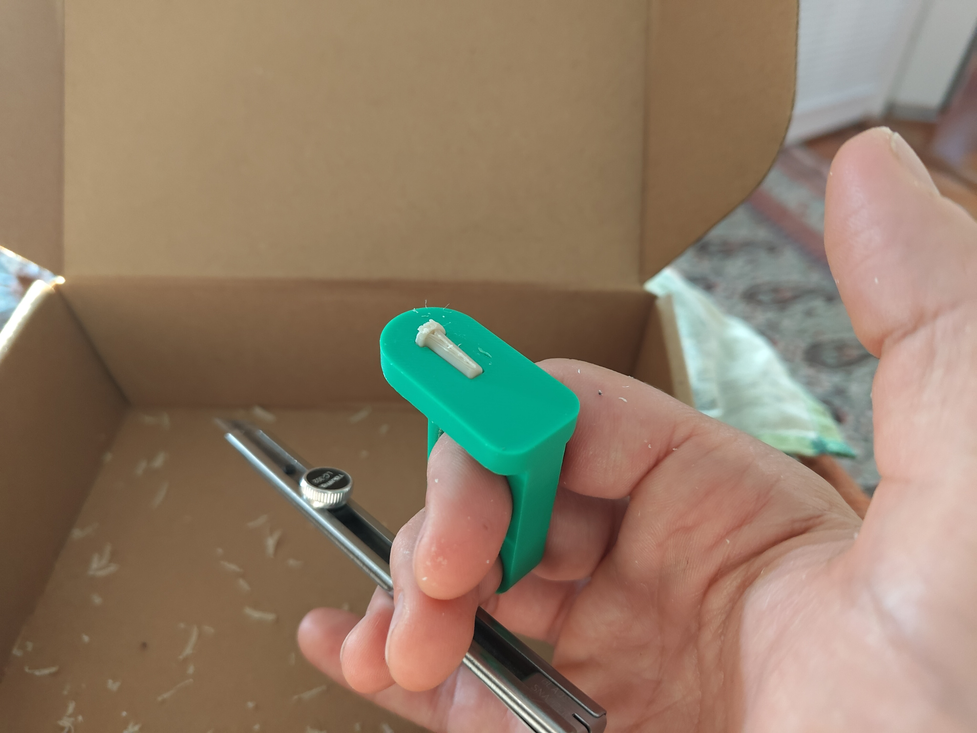
I designed and fabricated two tools to support PLAttice. One is a simple trimming jig for the pins, which must be printed parallel to the bed to keep layer lines facing the right way. This results in a small nub of plastic that I skim off with a razor. The jig protects fingers and makes this operation quite fast:
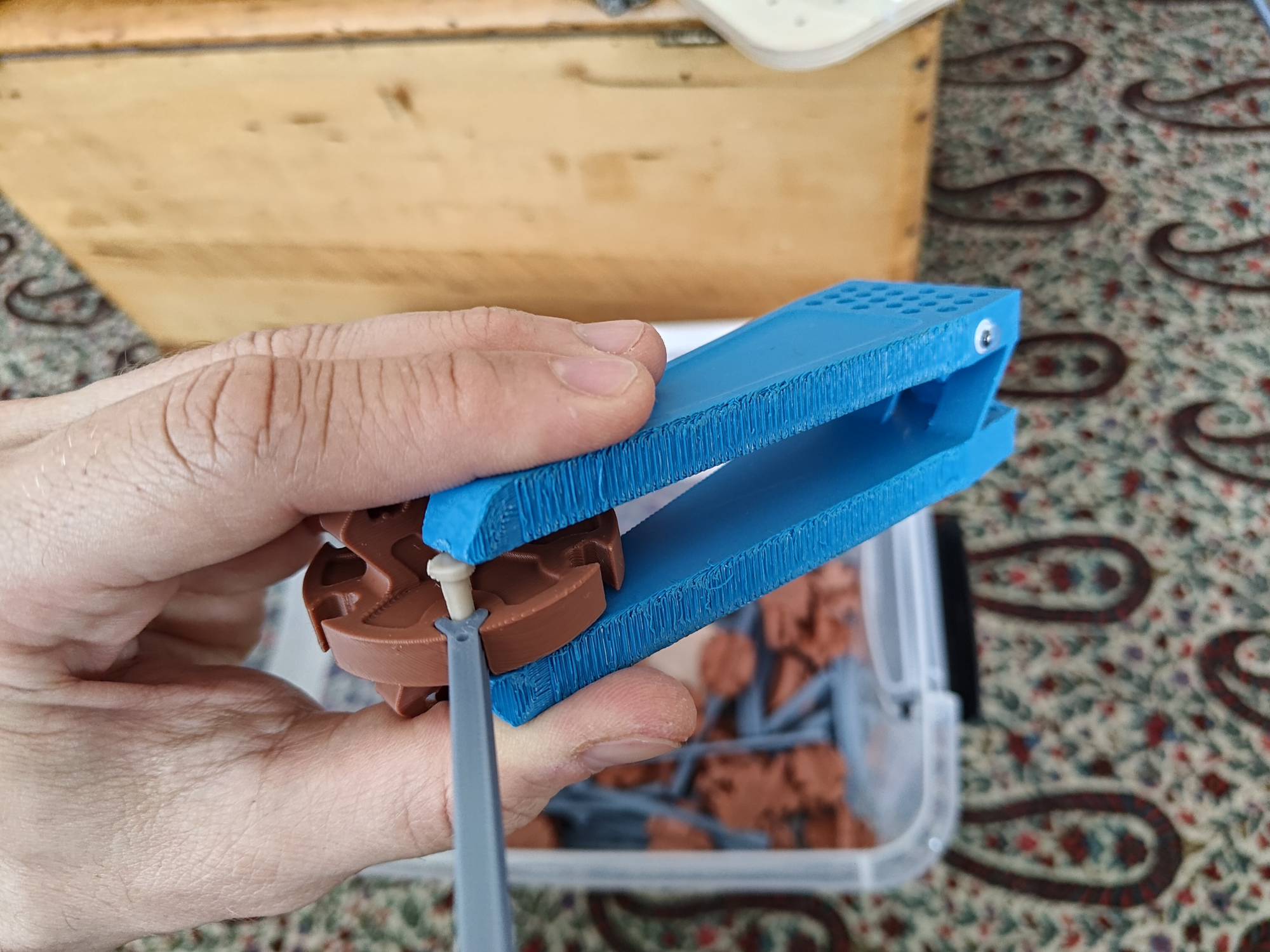
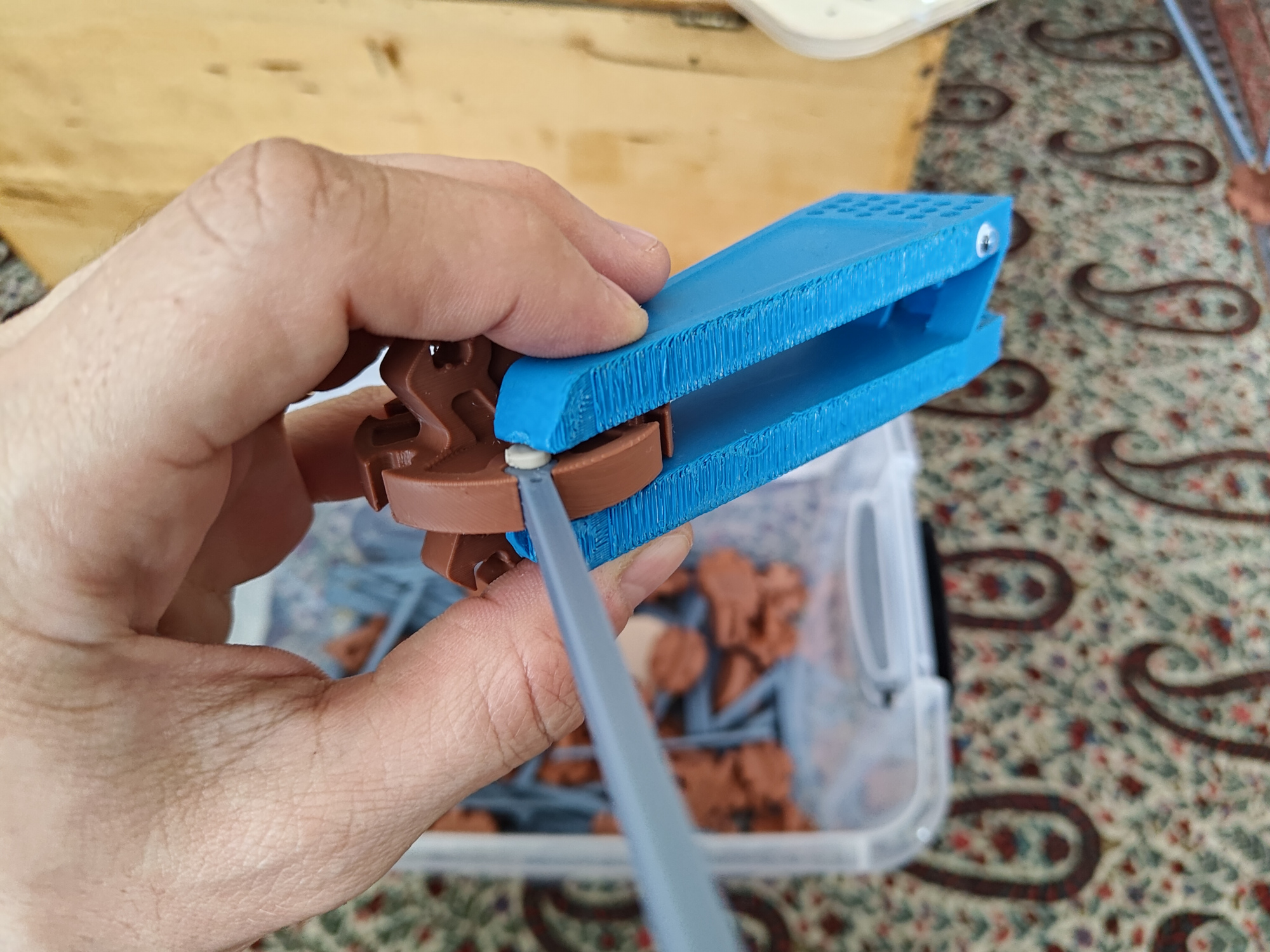
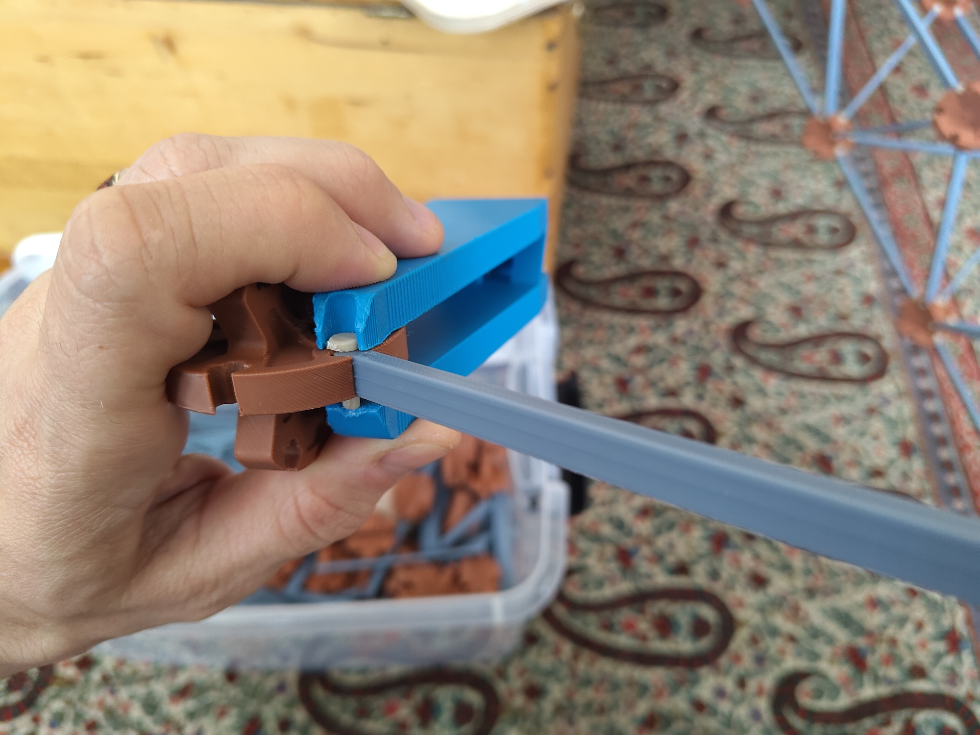
The other tool is a PETG assembly/disassembly chomper that helps drive pins home and pop them out. It comes off the bed in one piece and uses a small crossed-beam flexure as a pivot, and includes a bunch of holes in the handle to store extra pins (which are just a bit too big, so I don't usually try to use them):
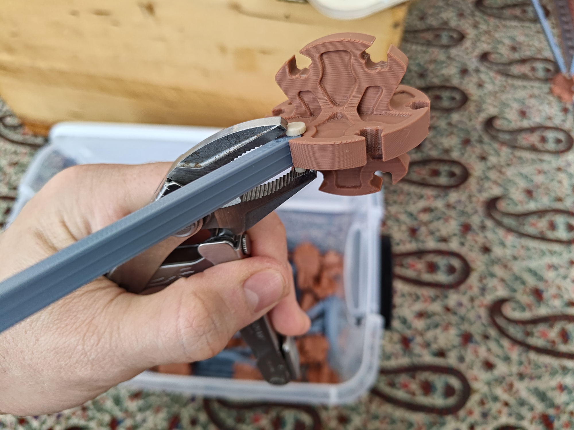
The chomper really could use another iteration, as the tip sometimes slips off the end of the pins during removal. I found that a small pair of locking pliers helps things along, but this is fussy to align and occasionally cracks pin heads:
This brings me to an important learning: PLAttice isn't a toy, because assembling and disassembling PLAttice isn't particularly fun. Perhaps it's "Type Two Fun", since one can still build interesting and satisfying and occasionally useful structures that seem fun in retrospect. But the parts are all somewhat sharp, and the chomper slipping off pins is a real bummer, and pre-inserting the pins before using the tool can be a bit painful on the thumb. I also found that I just wasn't used to handling 2-4 m stiff lightweight sharp structures in a small-ish space (my apartment) filled with breakable things. Nothing important was destroyed, but the walls and ceiling definitely have a few extra marks. And despite the assembly polarity marks -- dots on the struts, and inset areas on the nodes -- it is still annoyingly easy to lose track of rotational symmetry and assemble half of a lattice with the "wing" part of the node rotated the wrong way. The previously linked caning peg lattices, by contrast, are tons of fun because they go together and come apart with predictable and non-painful effort, and it's really difficult to put them together incorrectly.
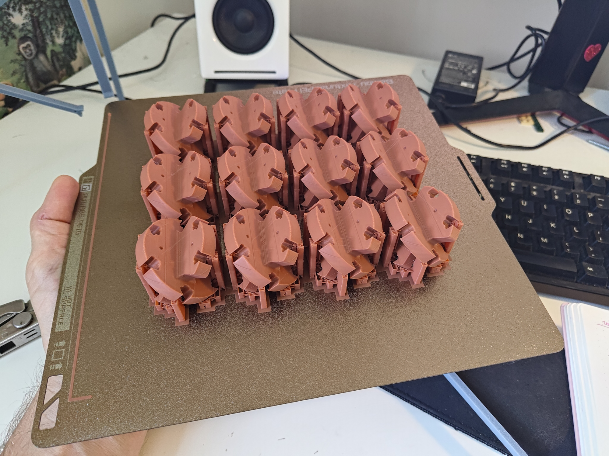
A few fabrication notes! Print orientation matters on all three part types, not just pins. Struts are easy, as they print without support material in their preferred orientation (flat on the bed), but nodes need to be massaged a bit. Printing them with any of the faces parallel to the print bed means at least a few of the joints will have weak spots and may break during pin insertion. Rotating them 45 degrees uses up a bit more support material but seems to produce much stronger parts. At 15% infill, 5 perimeters, and otherwise default settings, my P1S prints these in around 45 minutes each, so it's usually an overnight job when I need a bunch:
One meter of PLAttice box beam requires 80 pins, 60 struts, and 20 nodes. Once I got into the rhythm of production, I found I could print roughly this many parts in 24 hours: 1.5 hrs and 24 g for the pins, 7.5 hrs and 383 g for the struts across two plates, and 15 hrs and 414 g for the nodes. Support material removal and pin trimming is annoying, but only added a few minutes per day when I actually watched the clock. Still annoying.
If you have a 3D printer and a pile of PLA sitting around and would like to make some PLAttice, I'm releasing everything under the terms of CC-BY-SA 4.0. So go forth! Print lattices, assemble lattices, curse at lattices, sell lattices, and share new lattice designs (with a link back to this page and your modifications, plz), and let me know if you build a thing and I'll link to your docs.
ye olde files
struts, 60 per meter of box beam.
nodes (called "boxnodes" in Fusion360 archive), 20 per meter of box beam.
pins, 80 per meter of box beam.
short struts, just for end nodes.
end nodes, which only work on one side of a box beam (mirror for the other side).
adjustable end nodes, which only work on the other side of a box beam (also mirror-able).
feet, which screw into adjustable end nodes with some M5 hardware and need a larger bolt head hole; add a rubber pad for ceiling friction.
assembly/disassembly chomper, print on its side in PETG (not excellent for disassembly).
pin trimming tool, please don't cut yourself trimming pins.
end plate cutout pattern you can CNC route out of plywood, to bolt onto four end nodes with M5 hardware; add rubber pads for floor friction.
plattice STEP file with all of the parts (including plenty of drafts and abandoned ideas) from Fusion360. I got an unknown error when trying to export the Fusion360 archive, but I'll keep trying so you can see all of my poor parametric feature modeling organization "choices".
© copyright zach fredin, 2025